The signal strength and quality from the Hotbird satellite
did not seem to be as good as I expected from this 1 metre dish,
so the next stage was adjusting the position of the LNB.

'flute' The LNB support arms are made from ½ inch (12.7mm) diameter aluminium bar.

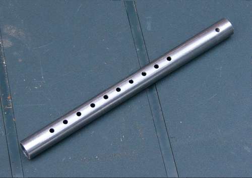
I obtained some 16mm OD, 14mm ID steel tube and made three of these 'flutes'.

There are 10 holes spaced ½ inch apart, then a gap of 2 inches and another hole.
saw-and-drill The next stage was to saw the support arms, slide the tubes over them and drill holes (see red dots) through them so that the arms could be re-assembled in their original positions using the "2 inch apart" holes in the tubes.
assembled An arm is moved to allow the tube to slide over it, then the two ends of the cut arm are re-aligned and the tube is slid over the 'join' and screws placed in the appropriate holes.

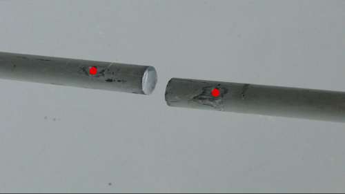
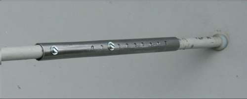
The further apart the screws, the greater the dish-to-LNB distance.
completed The ½ inch spacing between the holes in the tubes, combined with the adjustment of the LNB in its plastic collar, allowed me to experiment with dish to LNB distances of 370mm to 450mm
distance vs signal and quality The signal strength varied little at the different dish-to-LNB distances.

The signal quality "peaked" at 68%, but with a wide plateau.

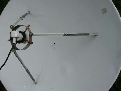
I set the distance at 410mm.

This is very close to the dish design dimension of 420mm (1 metre dish f/D ratio of 0.42), before going on to the next stage of adjusting the LNB skew angle.
LNB skew angle Again, the signal strength varied little at the different settings. This leads me to wonder just how useful this indicator is!

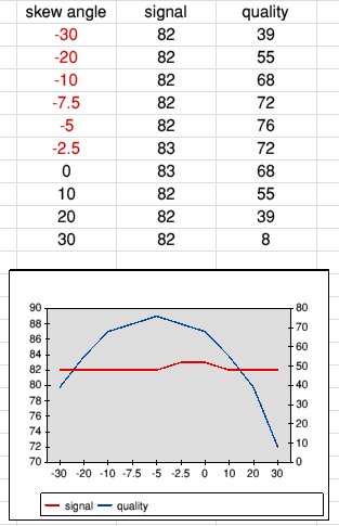
The signal quality readings proved much more useful.

Note that my zero degree skew is not necessarily zero with respect to the satellite. It is just my own "mark" so I could make adjustments relative to this "zero".

The LNB has marks moulded into the plastic at 5 degree intervals from -30 to +30 degrees. There was an obvious peak, in the symmetrical curve, at -5 degrees. This is where the LNB is now set.


Back Home