Experimenting with filters (Part 2) to try and improve reception of the low earth orbit
Meteor M2 weather satellite which transmits on 137.100MHz whilst maintaining good
reception of the NOAA weather satellites on 137.100, 137.620 and 137.910MHz
Parts list (and suggested suppliers)
4mm OD microbore copper tube (approximately 1.2 metres required for 2 coils *) - Ebay
* Theory suggests that each coil should be made from about 545mm of wire/tube
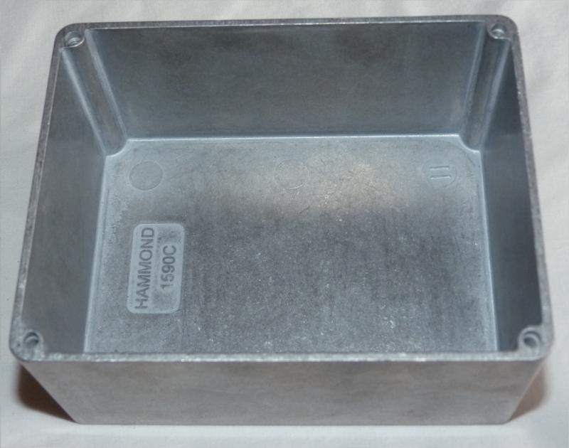
Aluminium Diecast box - Hammond 1590C (external size 119.5 x 94 x 56.5mm) - CPC
Small piece of aluminium sheet to make the divider.
2 x Single hole mount 50 ohm BNC sockets - CPC
2 x BNC T pieces - CPC
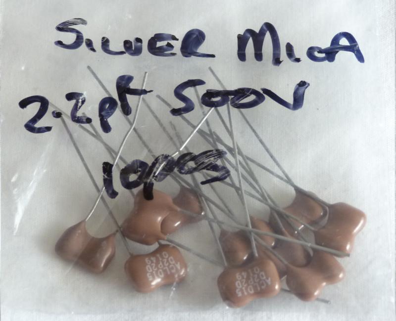
2 x 2.2pF silver mica capacitors - Ebay
A length of braid from RG58 coaxial cable
2 x Tubular, chassis mount, ceramic trimmer capacitors approximately 1-18pF - Found in my variable capacitor spares **
** My mother always says, "If you haven't used something for 5 years you should get rid of it".
Fortunately I don't always take her advice. I have probably had these trimmer capacitors for 30 years,
waiting for a suitable use for them.
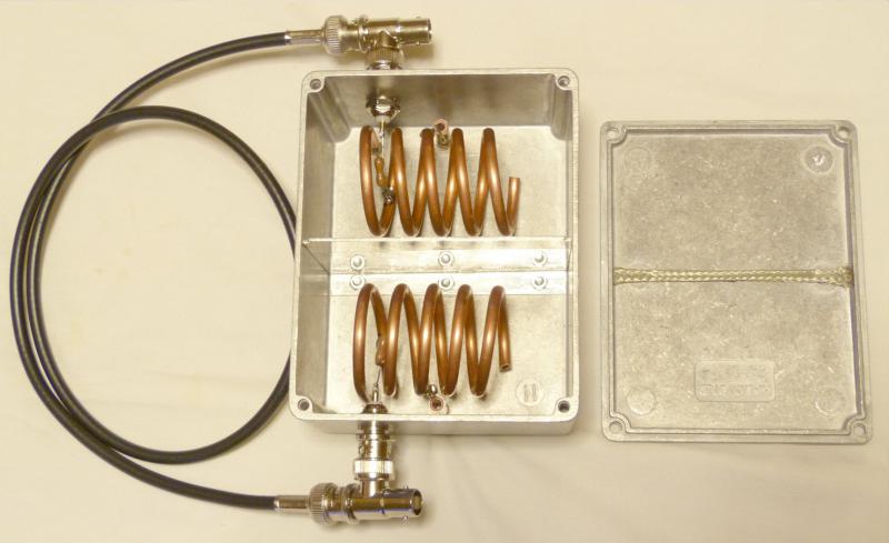
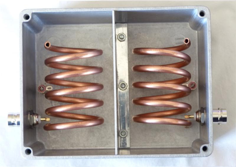
I made the divider a very good fit to the sides of the box so that coax braid would not be required
but this meant that braid on the top of the divider would have to be balanced on the divider while the lid was fitted.
Not having X-Ray vision I couldn't be sure of a good fit, so I opted to glue the braid, with a few drops of
"superglue" to the underside of the lid. Fitting the lid to the box there should be a very small see-saw
effect. This ensures that when the lid is screwed on there will be a good connection from the lid to the braid
to the divider.
The original design used a short length of coax inside the box, and passing through the divider, to connect the
"input" and "output" sockets. I opted for the easier solution of making an external connection via BNC T pieces.
This may introduce a small amount of extra loss.
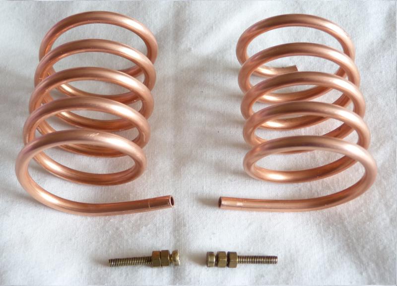
The original design used heavy duty solid copper wire for the coil (inductor). In order to make
the coil as stiff as possible I opted to use copper tube.
This is readily available on Ebay as copper "microbore"" pipe and I purchase 1.5 metres of 4mm OD pipe.
Rather conveniently, the bore of the pipe is very close to the diameter of a 6BA screw.
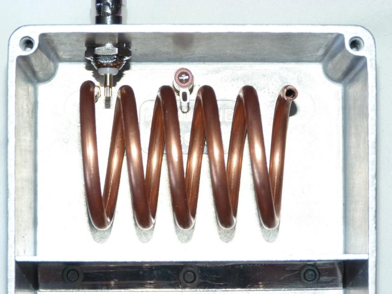
After winding the coils on a 30mm rod - this was easier than I expected; the tube does not kink and "stays put"
quite well - I soldered a 6BA brass screw into the "straight end" then sawed off
the screw head and placed a brass nut on the thread, to butt against the end of the tube.
The coil is fitted to the box by making the bottom of the diecast box the filling in a "nut sandwich" :-)
If you plan on building one of these filters I strongly suggest that after fitting the divider you work out
the position of the hole to mount the coil, then fit the coil.
Once the coil is in position you are able to see where the BNC socket and trimmer capacitor can be mounted
so that they do not foul the coil. Also make sure you have enough room to get
your soldering iron in to make connections.
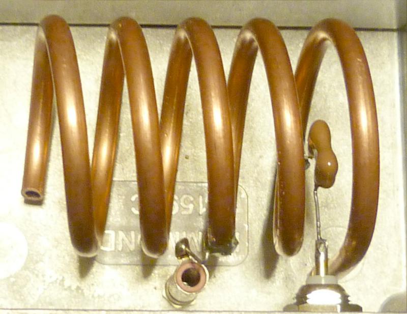
I worked out that the best assembly method was to solder one leg of the fixed capacitor and a short piece of wire
(to connect to the variable capacitor) to the coil before the coil was fastened into the box.
This just leaves the other end of the fixed capacitor to be soldered to the BNC socket and the short link wire to the variable
capacitor, after the coil is fastened into the box.
Trying to align my filter I found the frequency of the notch too low. In order to remove a few millimetres from
the open end of the coil I only needed (for each cavity) to unsolder the fixed capacitor at the BNC socket and undo
the 2 nuts fastening the coil and the variable capacitor. The coil and capacitors assembly could then be removed easily.
I used a "razor saw", often used with model railways, to remove the desired length from the coil.