IDEAS FOR MELTING SNOW AND ICE
Here are my suggestions for wind instruments and rain gauges
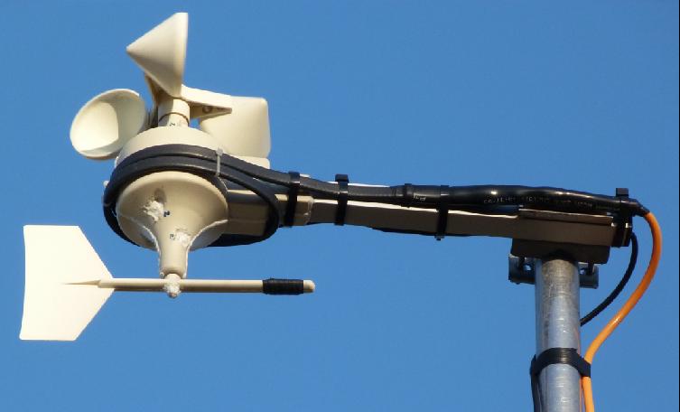
First, the wind instrument
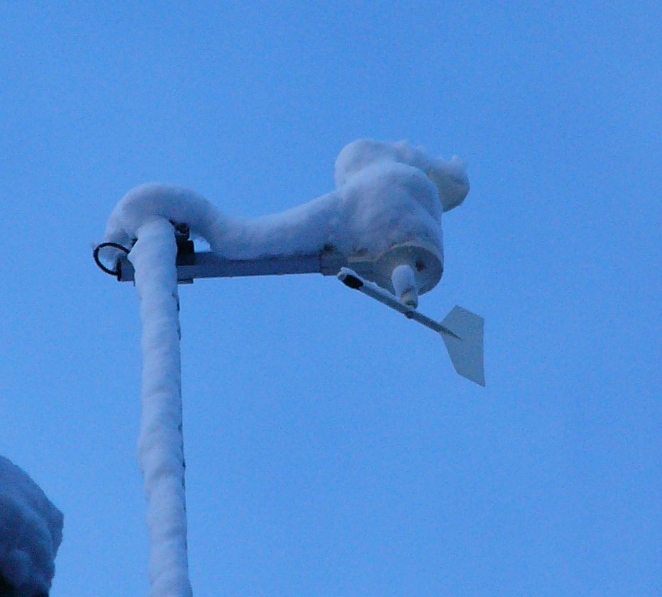
January 2010 - Frozen snow on the wind instrument
There are two options:
a) a heater on the inside of the instrument or
b) some method of heating on the outside.
With a) there is the advantage of whatever is creating the heat being protected from the weather,
but the disadvantages are that the heat has to travel from the inside to the outside,
and there is little space to install the heater inside the housing
With b) the advantage is that the heat does not have to travel through the instrument case
but a big disadvantage is that the heater must be weatherproof.
Fortunately there is a solution to this.
First obtain a suitable length of self regulating heating cable.
The type shown is rated at 36 watts/metre in ice, 18 w/m in air at 0°C.
As well as the heating cable itself, you will require termination kits for the cold lead connection and end seal
Wrap the heating cable around the outside of the wind instrument and the supporting boom, ensuring that it does not foul the movement of either the wind direction indicator or the anemometer cups.
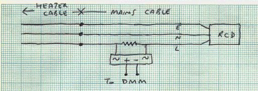
I have fed mine with orange mains cable via an RCD. It is not outdoor grade cable, so I'm not sure how long that will last, being subject to temperature extremes and UV radiation.
An optional extra is some method of monitoring the current drawn by the heating cable.
Digital multimeters that will measure AC current in the mA range, or AC volts, tend to be quite expensive, whereas a standard DMM that will measure DC volts can be purchased for less than £5.
I've used a 1 ohm wirewound resistor in series with the "live" wire. A bridge rectifier will then convert the AC voltage across the resistor to "raw" DC. This is adequate (unless you are looking for exact values of current) and will give relative readings (a lower temperature should result in higher current).
Because the mains cable and heating cable are "carrying" 230V AC, I thought that there might be some "interference" with the reed switches, electronics, or data on the 1-wire cable, but experiments indoors (before I put the instrument on the mast) and outdoors (installed on the mast) have given no indication of false readings from the wind instrument.
All I need to do now is wait until the wind instrument freezes up again, to see if the heater works as planned!
We had about 3 inches of snow fall in about 4 hours on 25th January 2013.
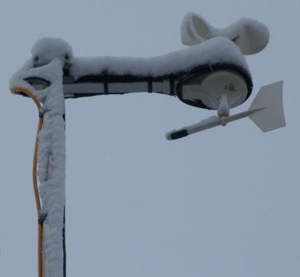
The following morning I took a photo of the wind instrument (above), then switched on the heater.
Within about 1 hour the snow had melted, but the temperature was already about + 3°C.
A better test would be to see what happens with temperatures below freezing.
Next, the rain gauge
Rain Gauge Heater (Snow Melter)
The following are suggestions if you want to fit a heater to the inside of a rain gauge.
There are bound to be other solutions and methods.
My first thought was to use another length of frost protection cable, like I've used on the wind instrument.
This would have to be mounted underneath the rain gauge base and hope there is sufficient rising heat to melt any snow in the rain gauge's funnel.
The problem with this method is supplying the 230v AC to something that is only about 6 feet off the ground, so I've discounted it for safety reasons.
Using a low voltage heating system, there are two options for temperature control: on-off and proportional.
An on-off system will have some hysteresis. Full power is applied to the heating element when the temperature drops below the lower "set-point"
and power is turned off when the temperature reaches the upper set-point. A fairly simple circuit using a thermistor as the temperature sensor
can operate a relay which connects (or disconnects) the heating element.
Such a circuit is available quite cheaply in kit form. It is the Velleman MK138 Thermostat kit.
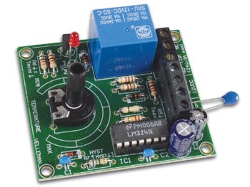
A search on Google Shopping will find a number of online retailers selling this kit.
It is also available ready built.
The circuit is shown at www.velleman.co.uk/manuals/mk138.pdf
As supplied, it is designed for a temperature range of approximately +5 to +30°C (41 to 86°F), but by changing
a few resistors the range (and hysteresis) can be altered.
The circuit requires 12v DC at 100ma, but the heating element can be powered separately via the relay,
the contact rating of the the relay being 24v AC or DC at 3A maximum.
A proportional controller applies just enough heat to try and maintain a constant temperature.
A circuit for this is slightly more complex. One such circuit uses the LM3911 temperature sensor IC.
Typing LM3911 into Google will show a number of web pages containing the datasheet for this IC.
The disadvantage of this circuit is a) the IC appears to be obsolete and therefore is scare and commands higher prices (see Ebay)
and b) it will not be available in kit form.
Just like the Velleman circuit, the heating element is powered separately from the sensing circuit, but this time is "switched" via an opto-isolator. Pins 5, 6, 7 and 8 of the 8 pin DIL version are used to attach the IC to the temperature source.
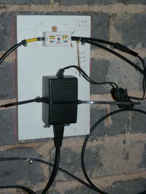
The CAT5 cable running from the 6 way hub to my temperature/humidity sensor and rain gauge has 8 cores.
Pins 4 and 5 for data and ground and pins 7 and 3 are used for unregulated voltage (approx 14v in my case) and ground.
I have removed the link on the hub pcb that provides a regulated 5v supply on pin 2.
I can use the 14v voltage/return for a low power feed to a heater control circuit.
By installing a "breakout box" indoors, the remaining wires (1, 2, 6 and 8) can be "doubled up" to provide a feed/return for a heating element.
The advantage of doubling up is that it halves the cable resistance and by using a higher voltage I can reduce the current.
Using 16, 470 ohm resistors in parallel the heating element becomes 29.375 ohms. With 24 volts this will draw approximately 0.8 amps.
www.calculator.net/voltage-drop-calculator.html shows that feeding 24v to 20 metres of 24awg wire, the voltage drop will be 2.7v at 0.8A.
Doubling up on the conductors will halve this to 1.35v. So I would have (24-1.35 x 0.8) = 18.12 watts.
Hopefully this will be sufficient to melt snow, if the heat is applied in the right place.
The ideal location for the heating element is on the underside of the rain gauge funnel, and the temperature sensor (thermistor or LM3911) close by.
Wherever these are mounted you must ensure they don't foul the tipping bucket.
Physically attaching the heating element to the underside of the funnel means that some method of disconnecting it is required
for when the funnel needs to be removed for cleaning, so a connector with a minimum of 2 pins is required. More pins is better so that
in the event of a poor contact on one pin, the heater should still be getting enough power. I decided to use a 4 pin connector (with gold plated pins).
The choice of connector is quite important. Ideally you need something which is easily disconnected with one hand
while the other hand is holding the funnel section of the rain gauge.
I've decided to build the Velleman kit and install that, while working on the design and build of an LM3911 circuit.
I will install the wiring to the rain gauge to enable an easy changeover from one to the other.
With the Velleman kit that I have, there is an error on the pcb silk screen. The markings for R1 and R2 are transposed.
This isn't really a problem as both are 1k resistors, but may have caused some confusion if I needed to do any fault-finding.
After building the kit as supplied, I taped the thermistor to a small heatsink together with the thermocouple from a digital thermometer I have.
The heatsink helps to slow down temperature rises and falls, allowing for more accurate checks to be made of the switch-on and
switch-off temperature.
To reduce the temperature of the heatsink (and therefore thermistor and thermocouple) I used a can of freezer spray.
I found that the temperature range went well below that suggested by Velleman. After some experimentation I changed
the preset from 100k to 22k (to allow better "fine tuning" of the switching point) and R5 from 120k to 180k.
For R4, R5 and R6 I have used metal film resistors, rather than the carbon film ones supplied.
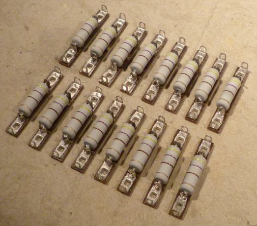
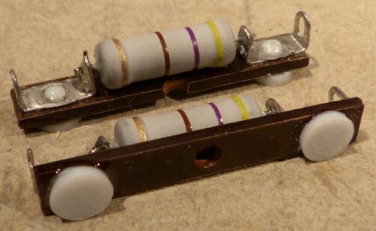
Mounting the heater resistors
I've used 16, 470 ohm 3W metal oxide resistors in parallel. Each resistor has been mounted on a section of tagboard.
Not being able to see how much space there is inside the rain gauge with the cover/funnel fitted, it is difficult
to know whether these resistors, when fastened in place on the underside of the funnel, would foul the cylinder which
houses the pcb. They may well have done.
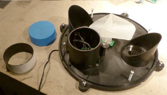
Looking inside the cylinder, there is plenty of room so I decided to remove 1 inch from the top.
I cut a strip of paper 1 inch wide and taped it round the cylinder as a guide. You might wonder why I didn't use the blue cap
as a cutting guide. With the blue cap fitted, I would not be able to see inside the cylinder while sawing off the top 1 inch and
may have damaged the pcb or cables. With no cap, it was easy to hold the pcb and cables away from the saw blade.
If I glue the tagboard to the underside of the funnel, the metal contacts on the underside of the tagboard will be in
direct contact with the plastic. This is likely to melt when soldering the tags, so some form of stand-off or insulation
is required.
One solution is to put a "bead" of epoxy glue on the contact (and let this harden before gluing the tagboard
to the plastic). Another solution would be to use a nylon screw, with the head acting as the spacer. Checking the hole
diameter with a twist drill, I found it to be just over 2mm. An experiment with a nylon screw proved that nylon wasn't
going to be suitable.
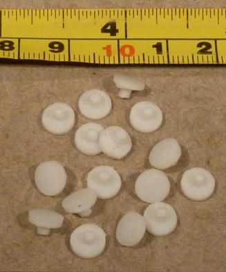
PTFE would be a better option, but I would have to make my own spacers. I turned some "screws"
(no thread needed) from 6mm diameter PTFE rod.
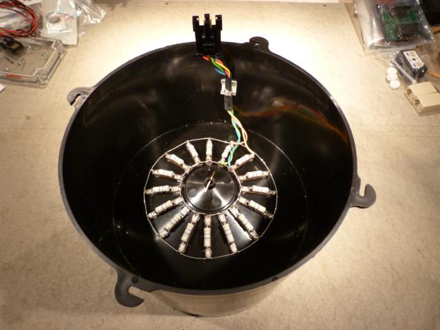
Fitting the resistors/tagstrips on the underside of the funnel evenly, is helped by the moulding marks in the plastic.
Once glued (I've used a 2 part epoxy resin) in place they can be wired up (all in parallel).
I used some aluminium foil in the area where I was soldering
to catch any beads/drips of solder and prevent them melting the plastic.
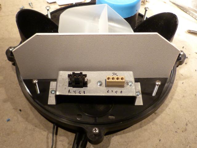
The connecting cable is held well out of the way of the tipping bucket by using a self adhesive cable clamp.
I made an aluminium bracket to support the 4 way heater element connector and a 4 way connector block for the temperature sensor.
Only 2 contacts are required for the Velleman thermistor, but all 4 would be needed for the LM3911 circuit.
Recently, the lid of my Stevenson screen needed replacing. It was made from plywood and painted. Years of rain has had its effect
and the wood was becoming rotten. I purchased a small sheet of 2mm thick white ABS and made a replacement lid. I had some left
over and have made a screen for the inside of the rain gauge, to protect the connectors from water that might splash around when the bucket tips.
I've slid a length of heatshrink tubing over the thermistor (but not shrunk it) to provide a little protection.
I connected everything up indoors and (using the freezer spray and my digital thermometer) adjusted the heater control circuit
to switch on at approximately 3°C
The last step, before installing the rain gauge and heater control circuit outdoors was to check the accuracy of the rain gauge.
My calculations showed that for this rain gauge, with its 8 inch diameter funnel, 82 grams (= 82 ml) should provide 10 tips of the bucket corresponding to 0.1 inch of rain, and as supplied it was very accurate and no adjustments were required.
And now I'm waiting for some good weather to install the units then hope for some snow to see if it works!
I'll update this page with my findings...
Everything now installed...
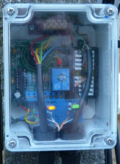
The Velleman circuit includes a red LED to indicate when the relay has switched (and therefore when my heater is powered). I've added 2 more LEDs to show that the 1-wire voltage feeding the control circuit (approx 14 volts in my case) and heater supply (24v) are working normally.
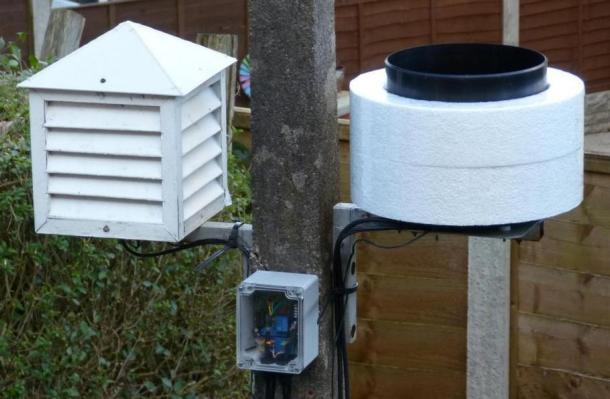
I've fitted everything in a waterproof box with a clear lid, on the mounting post supporting the rain gauge (and Stevenson screen). This can be seen from my kitchen window. The circuit appears to be working well, but we have not had any snow yet to test it fully.
A suggestion by Torvald Konstali, made on the 1-wire weather mailing list was that I should insulate the rain gauge, so that is the next step.
Initially the heater was set to come on at about 3°C. There was a little snow early in January 2013 - about 0.5 inches.
When I checked the rain gauge later I found a small lump of ice. Obviously I was not using enough heat, so increased the temperature setting.
On the evening of 25th January we had about 3 inches of snow in 4 hours but the rain gauge did not register any "rain"
until it had stopped snowing and it took about 24 hours for all the snow in the rain gauge to melt.
I needed even more heat!
I have increased the setting again and have made an insulating ring out of polystyrene, which slides over the gauge.
It's quite a snug fit to prevent it being blown away in strong winds.
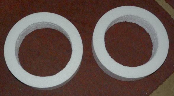
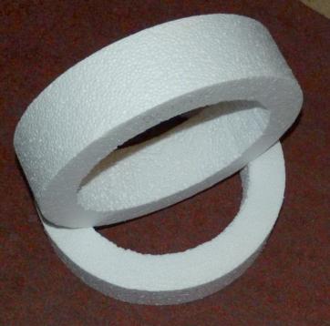
The insulating ring should reduce heat loss from the wall of the gauge and allow more heat to rise, hopefully melting snow faster.
I now await more snow! That could be in the next few days, or in 12 months time!
In the meantime I am monitoring the heater to see how often it comes on, and how long it remains on, at various temperatures.
I intend to plot a graph of % "on time" versus temperature. This may give me some indication of how low the temperature has to fall
before there is insufficient heat to maintain the temperature (i.e. when the heater is on 100% of the time.)
I'll update this page when I have some results.
A few results... added 10/03/2013
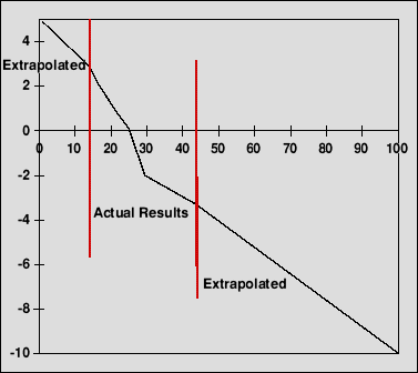 |
The graph shows the temperature (vertical scale) versus the percentage "on time" of the heater (horizontal scale)
The "% on time" is calculated by noting the time at which the heater switches on (a), switches off (b), and switches on again (c).
I then calculate (b) - (a) / (c) - (a) * 100%
Extrapolating the line in both directions suggests that the temperature can drop to about -10°C before the heater is unable to maintain a temperature, inside the rain gauge, of about +5°C
Fortunately, it rarely gets that cold! |